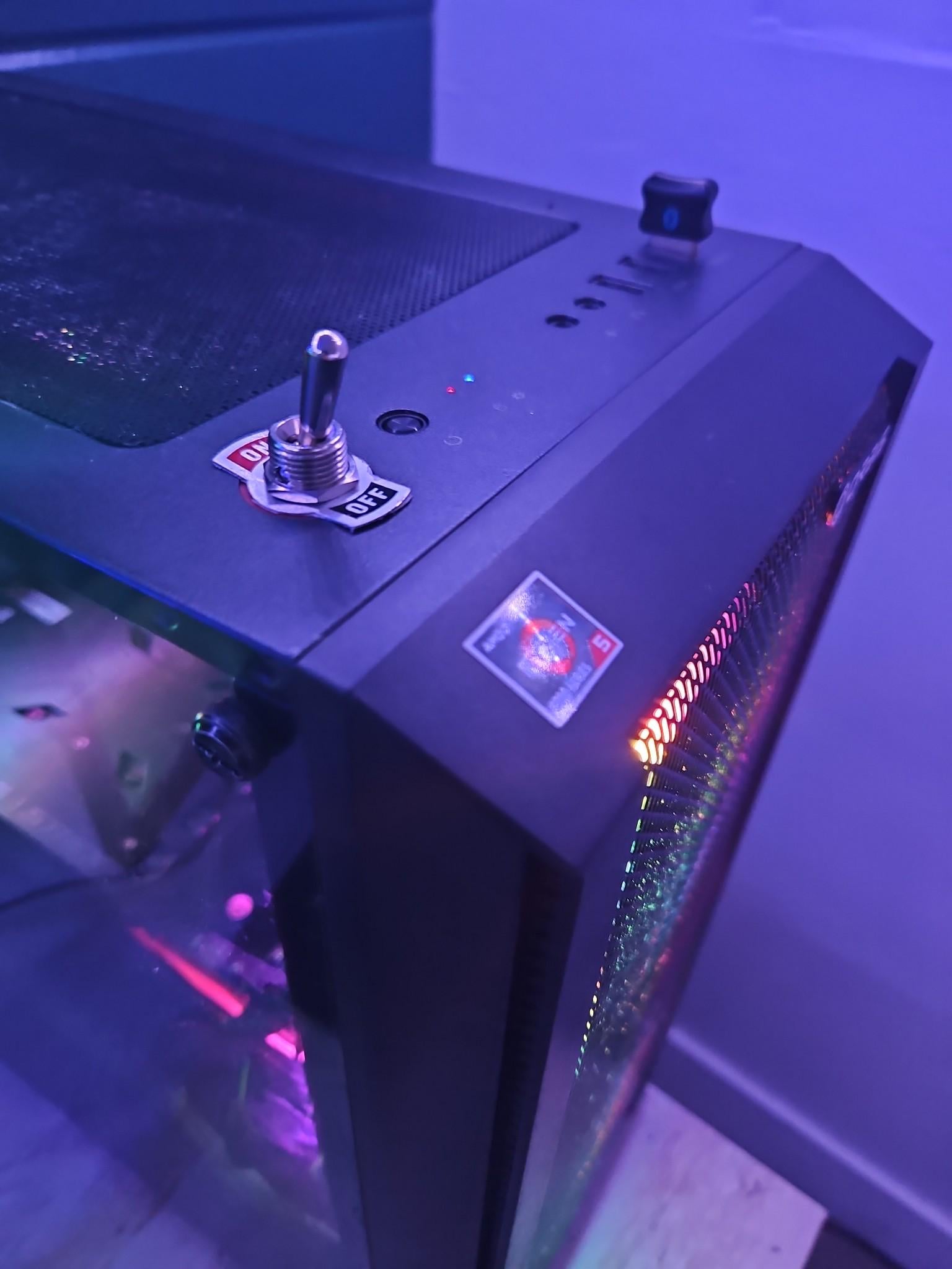
Works but still functions like a button(you have to turn it on and then off again to boot) but fatefully my gpu decided to die on me a week later so I’m slowly earning for that now lol wish me luck

Works but still functions like a button(you have to turn it on and then off again to boot) but fatefully my gpu decided to die on me a week later so I’m slowly earning for that now lol wish me luck
8 Comments
I can’t have that, I’d want to keep flicking it back and forth.
Neat mod! I helped an acquaintance of mine diagnose a broken power button. I should ask what his solution for a new button was
What you need is a momentary switch, it rocks forward to start, then moves back to the closed position on its own.
Edit: and you can get them with flip open covers too.
If you need a day project, order an Arduino nano and you can make it into a functioning switch, but there’s gonna be some rewiring necessary.
1. From the motherboard 24 pin connector you’re gonna need to splice into the red (5V), purple (5V standby) and black (ground) wires.
2. Plug 5V standby into the Arduino’s 5V input, ground to ground, 5V into any digital pin (let’s say D3 for reference). I would also put a 1kOhm resistor between 5V and D3 just for peace of mind and to protect from a short if you mess something up in code.
3. Put a ~50kOhm resistor between ground and D3
4. One end of the switch goes to ground, other to another digital pin (D4)
5. Some multimeter measuring comes in here. One of the motherboard pins is either 5V or 3.3V, the other is ground. note which one is which before proceeding.
6. Connect a NPN transitors [as shown here](https://europe1.discourse-cdn.com/arduino/optimized/4X/8/c/b/8cbc249b50b804b9dbad8d177e7950321c7048e2_2_500x377.png). The resistor is 330 Ohm, base (middle pin of the transistor) goes to an Arduino digital pin (D5), ground pin goes to emitter (right one if you’re looking at the flat side), positive goes to the collector.
That’s it for the wiring, for the code you need to set it up as follows:
1. D3 is input, D4 is input_pullup, D5 is output
2. read the signal from D4 (switch) – figure out which is which (example – high is on and low is off or flipped)
3. Read the signal from D3 (PC 5V), high means the PC is on, low means the PC is off
4. Compare them, if they’re not the same activate D5 to virtually press the power button.
5. You can mess with debouncing to prevent unwanted shutoffs or shutdowns, but I would just set a 1000ms sleep after every loop so you’re not polling too often, plus a 3000ms or so sleep after activating the virtual power button and it should work just fine without any debouncing.
You can find many arduino coding tutorials online, ask ChatGPT or feel free to DM me if you decide to go through with this and need help with the code.
I just made something similar for my new build but with a momentary key switch. Awesome!
Ah, I see you dont have a cat
It’s cool, but imagine the magnetic key / code panel power on
I have my pc mounted in a wall and I have a button on my desk that turns it on from like 5-6 feet away