
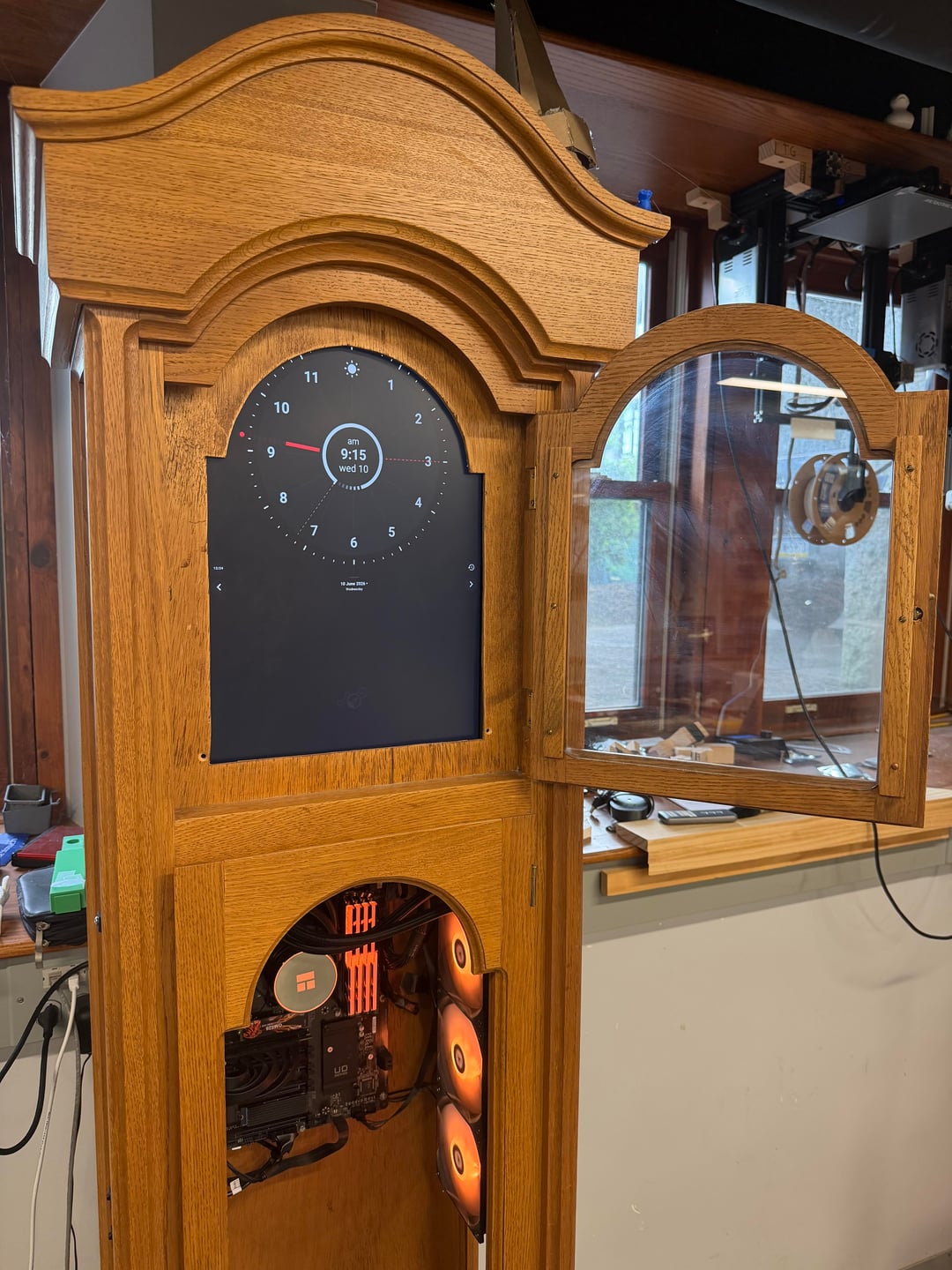
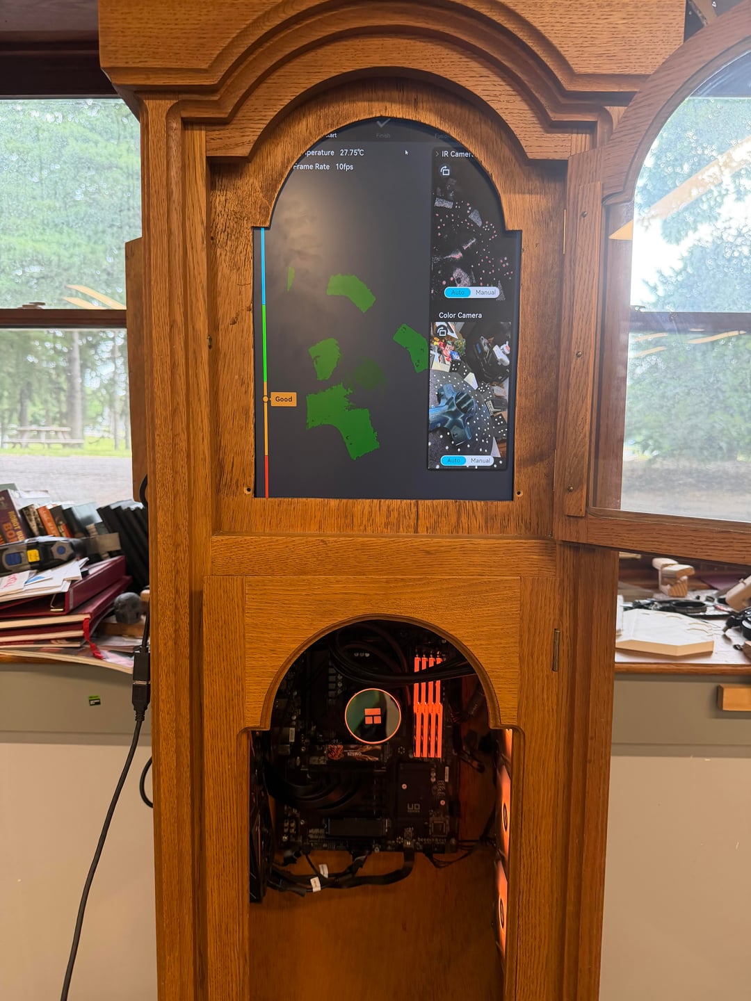
A few months ago, my engineering teacher (who has a killer mustache by the way) challenged me to put a desktop computer inside his grandfather clock that happened to be in the lab. I gladly accepted and got to work designing what is most definitely my craziest project yet.
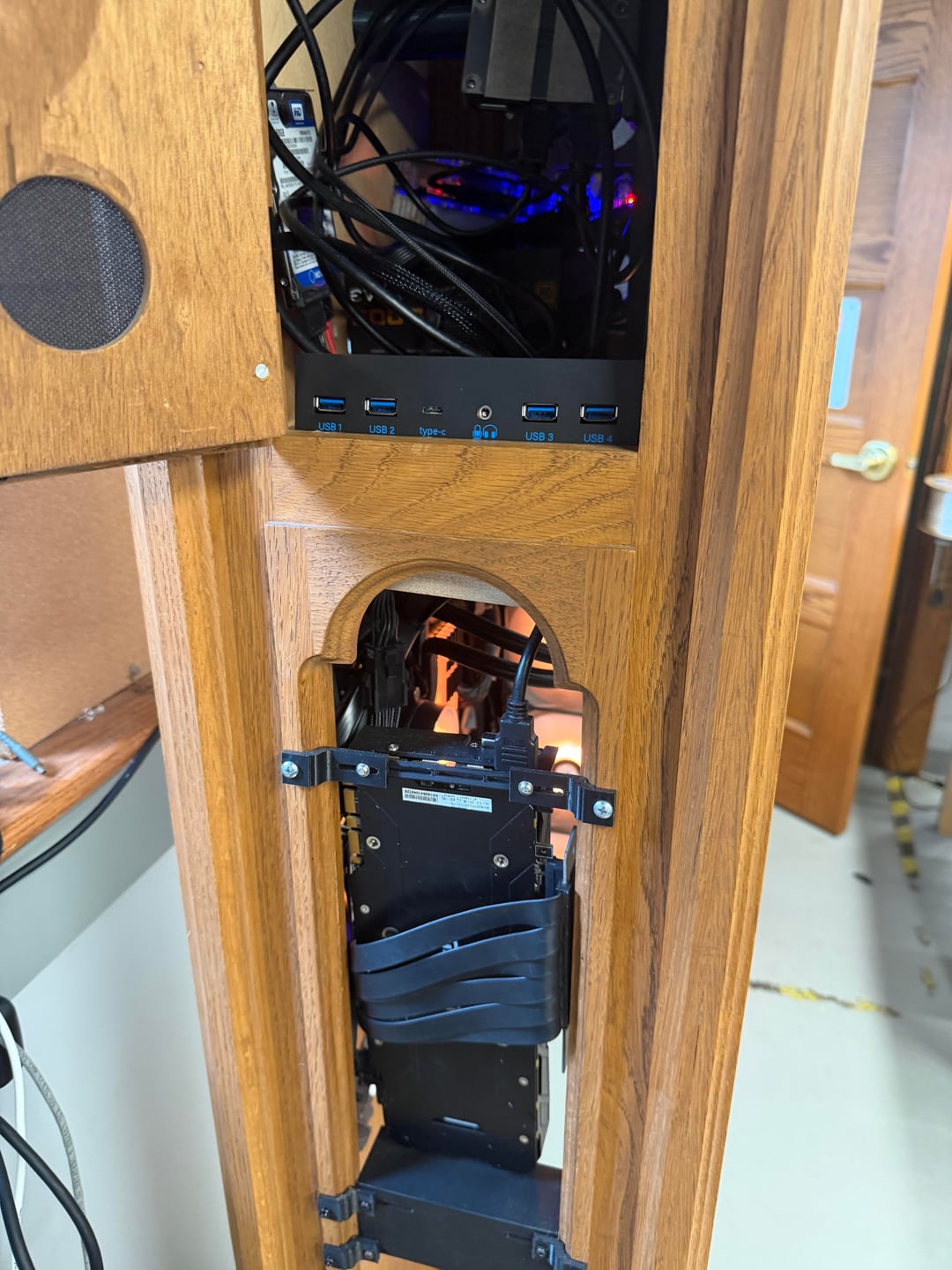
The design I envisioned from the start was similar to those of wall mounted PC's, but instead of everything being flat against the back of the clock, we'd have the liquid cooler and the GPU (via riser cable) mounted to the side openings. As for the monitor, it would sit above the PC itself where the dial assembly used to be, along with the power supply stowed away behind it.
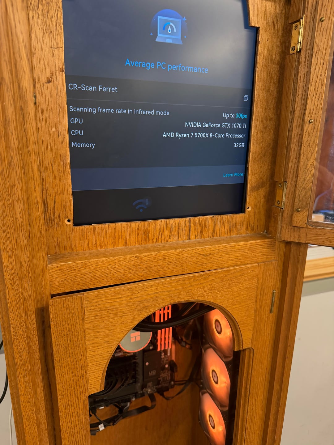
With a general idea for the design down, it was time to start working on the specs. The computer would be used for 3D scanning, so I started doing research on what parts of the PC 3D scanning would stress most. I came to the conclusion that a strong CPU and a moderate amount of RAM are really the only two things that matter. The 5700x was an obvious choice at the time; a modern octa-core processor for only $140 was a no-brainer. I also got a refurbished B550, 32GB of RAM, a good-looking Thermalright AIO, and to top it off, a used GTX 1070 Ti.
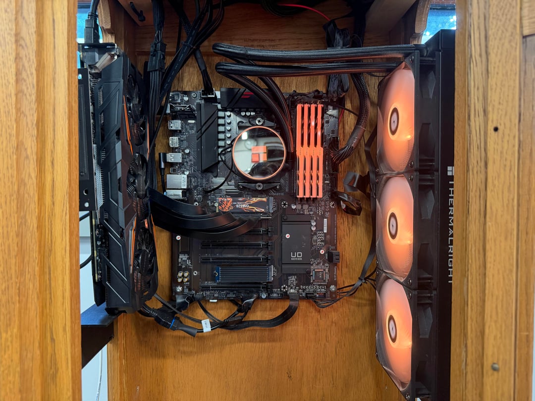
Before I started throwing everything into the clock, I assembled the PC first, installing Windows, drivers, and configuring the RGB to match the hue of the clock. Then, I started marking up where the standoff holes on the motherboard lined up with the clock's backboard, so I knew where to drill. Next, I inserted the AIO into the opening on the right side of the clock, and to my surprise, it fit perfectly. I'm not kidding when I say if either the clock or the AIO were even one mm larger, it wouldn't have fit. Friction held it in so tight that I was convinced we didn't even need to 3D print a mounting bracket, but my teacher, being the experienced engineer he is, said it was worth the extra effort to prevent issues in the future.
With the motherboard and AIO both accounted for, I decided to mount them first and then tackle the GPU afterwards. I drilled holes where I marked, and then installed standoffs for the motherboard to sit on. After that, I slid the AIO into place and connected it to the mounting brackets I 3D printed and installed ahead of time. Next, I moved on to the GPU, and believe me, this was the hardest part of the project. Mounting the GPU vertically was actually quite simple; the issue was the riser cable. It only plugs in one way, and to have the GPU fans facing inward meant it would have to wrap around the back of the GPU to make it to the PCIe slot. It was only barely long enough to make the run, and that solution took many class periods to figure out.
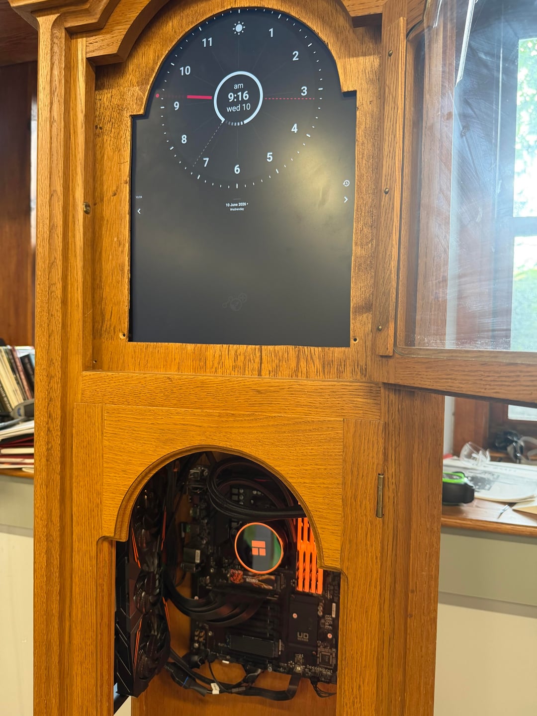
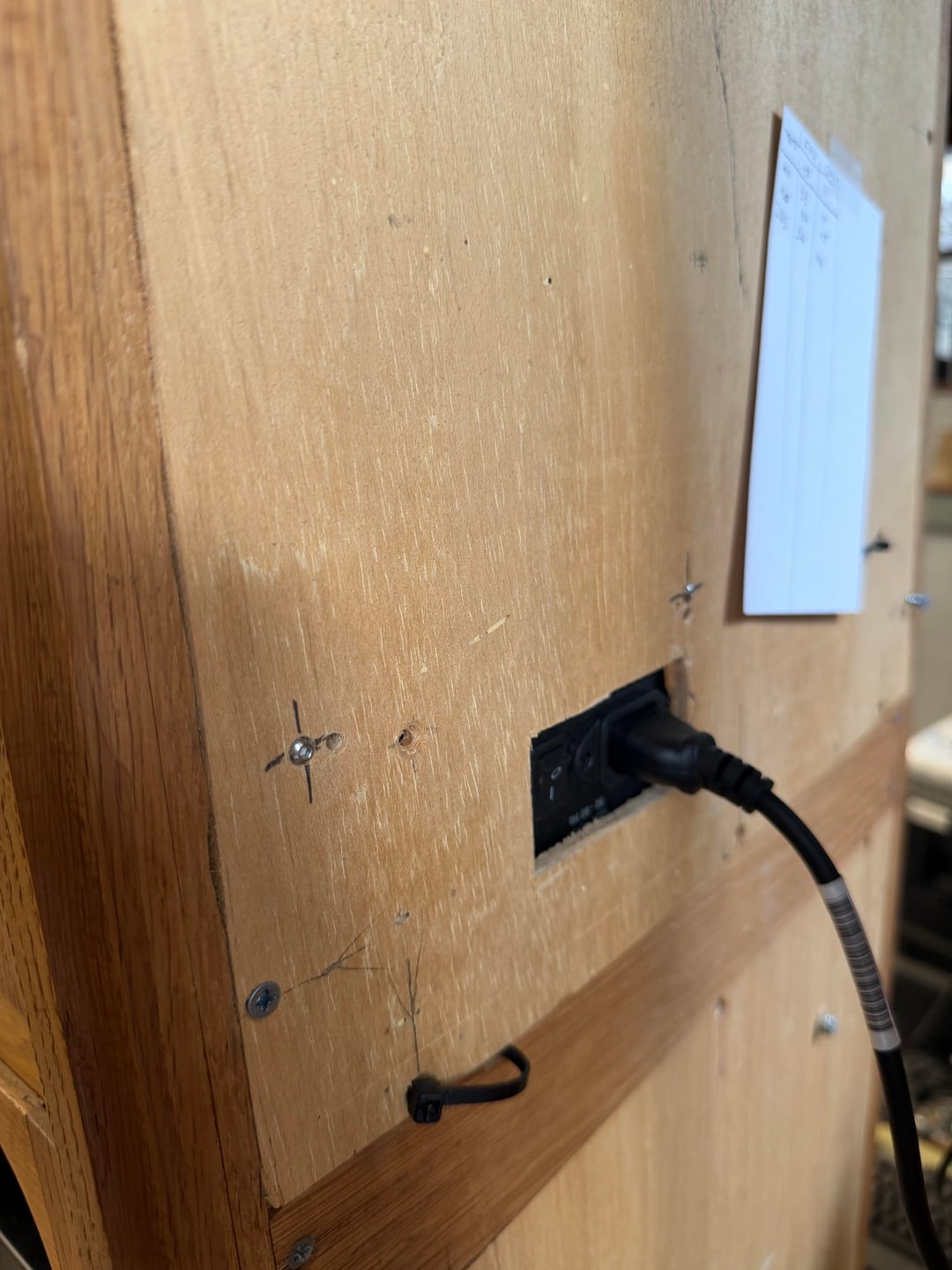
Moving on to the top half of the clock, I targeted the power supply installation first. This was by far the easiest step, as the standard ATX PSU mounting pattern is designed to distribute weight evenly, so all I had to do was drill four holes (plus a cutout for the AC cable) and bolt it into place. My final goal was to mount the monitor in a way that looked natural, while not taking up too much valuable space or interfering with the power supply. My engineering teacher designed and 3D printed a simple VESA-compatible adjustable pole that uses tension to force the monitor up against the previous clock face's outline. There are no screws or brackets, but it's the most elegant solution we could think of without either taking up more space or ruining the design of the clock.
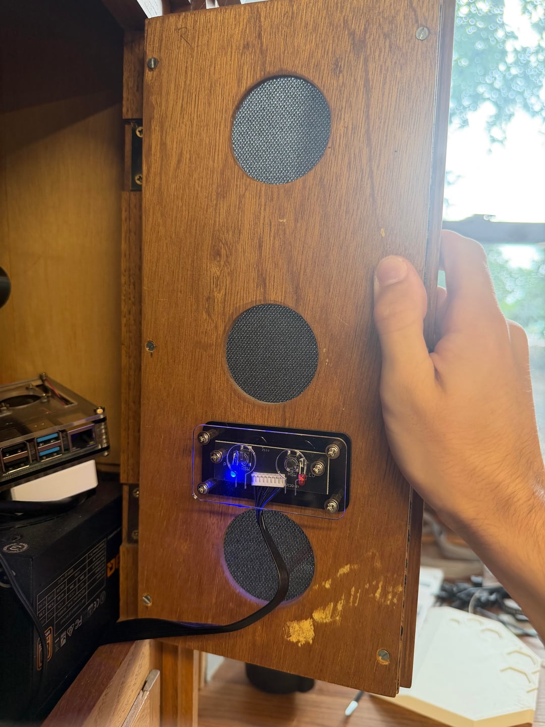
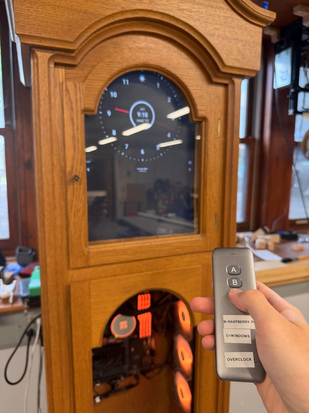
All that's left are the final touches! I installed a standard 3.5-inch IO module in the upper compartment behind an access door for ease of use and concealment when necessary. Then, my teacher had emphasized that he wanted me to keep the clock's original functionality intact. So I used a Raspberry Pi and some software a friend developed to display the time and his class schedule on the clock whenever he didn't need the PC. And to control inputs, I picked up an RF remote-controlled HDMI switcher so he can easily check his schedule or the time without having to reach inside the clock to select the Pi's input. The last step is to install the power button. I placed it on the right-side access door itself, so when the door is open, the button is facing the user.
After about three months of work, the Grandfather Overclock boots! I can't thank my engineering teacher enough for his guidance and 3D modeling skills throughout this whole process. Oh, and a big thanks to my school for funding this project too. If you have any questions about this project, I will answer as many comments as I can.